Local Tone Mapping
1. Introduction
The development of high dynamic range (HDR) imaging technology allows us to capture scene information that far exceeds the brightness range of traditional display devices. However, whether it is a monitor, a mobile phone screen or a paper print, the displayable brightness range is much smaller than the dynamic range of the real world and HDR images, thus forming the so-called "dynamic range gap": we record far more information than the display device can directly present.
Tone Mapping was proposed to solve this problem: without changing the physical capabilities of the display device, HDR images are mapped to a low dynamic range (LDR) space by non-linear compression of image brightness and contrast, while retaining important visual details and subjective feelings as much as possible. Different from "global tone mapping" which is only based on global statistics (such as global logarithmic curve, γ curve), local tone mapping (Local Tone Mapping) adaptively adjusts the mapping behavior according to the local context around the pixel, thereby better preserving local contrast and texture details.
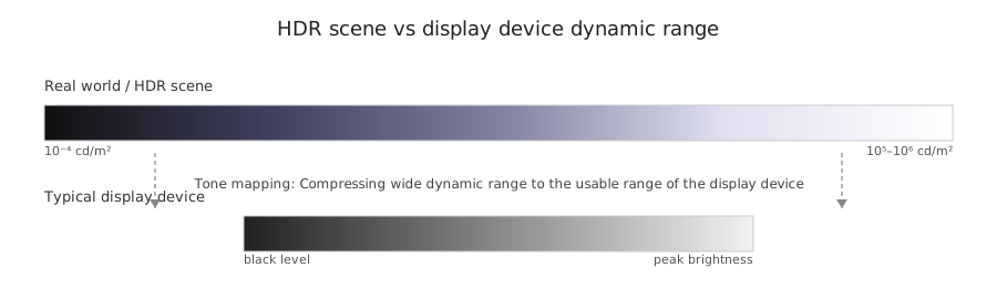
Figure 1: HDR scene brightness range and display device dynamic range.
1.1 Dynamic range gap between HDR imaging and display equipment
The real-world brightness range can span several orders of magnitude: from the dim starlight of the night sky to the clear midday sun, brightness ratios may reach over 105–106. Modern HDR cameras and multi-exposure compositing techniques are capable of recording a wide range of brightness and storing them in floating point or high bit depth formats. However, the contrast and peak brightness of mainstream display devices are still limited, and even HDR displays cannot fully restore the full dynamic range of real scenes.
If HDR content is directly displayed linearly on an LDR display device, either the highlight area will be completely overexposed and details will be lost, or the dark area will be completely black and difficult for the human eye to distinguish. How to reasonably allocate "brightness resources" within the limited dynamic range to make the picture both hierarchical and readable has become one of the core issues of HDR display.
1.2 Why tone mapping and "local" tone mapping are needed
Traditional global tone mapping uses a unified non-linear curve (such as logarithmic, S-shaped curve) to compress the entire image. They can control the overall contrast and brightness relatively easily, but it is often difficult to take into account the details of both bright and dark parts at the same time:
When the compression range is large, the overall contrast is weakened and the picture appears "gray";
When a certain brightness area is emphasized, detail may be lost in other areas.
Local tone mapping designs different mapping behaviors for different spatial locations by introducing local neighborhood information. For example, in scenes with strong backlight, local tone mapping can improve the local contrast in shadow areas of people without excessively compressing the brightness of the sky, making facial details clearer. This ability of "spatial adaptation" is the main advantage of local methods over global methods.
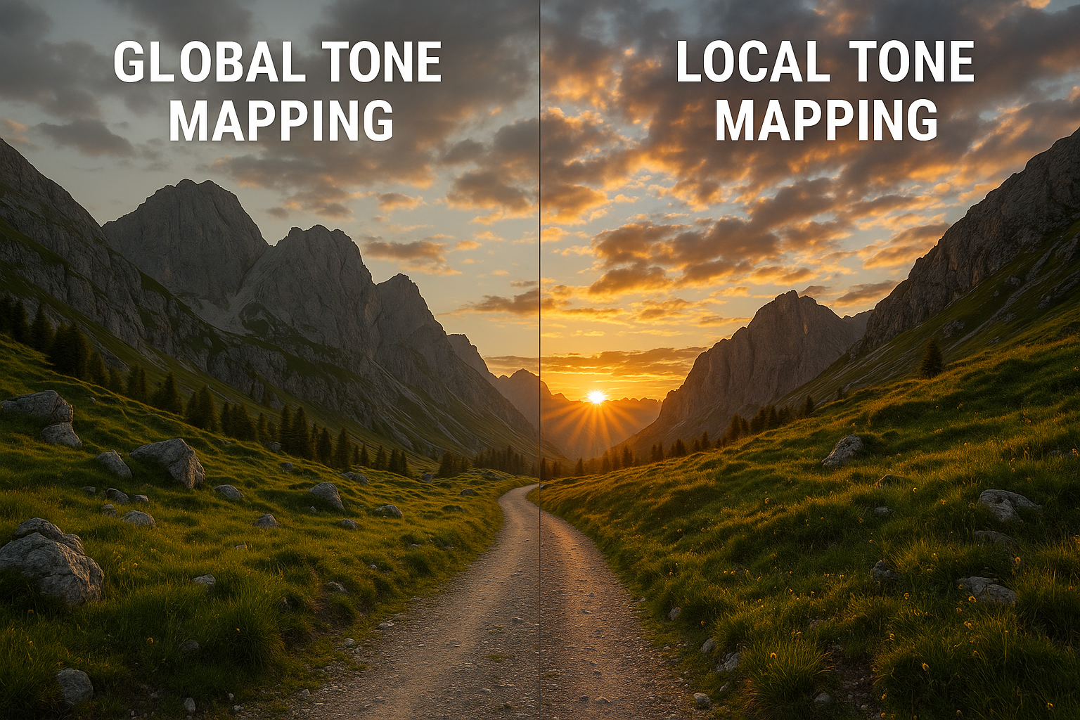
Figure 2: Real-scene comparison example of global tone mapping versus local tone mapping.
2. Tone mapping basics
2.1 Human visual system and logarithmic response characteristics
The subjective perception of brightness by the human visual system is not linear. A large number of psychophysical experiments show that when the physical brightness increases by a fixed multiple, the brightness changes perceived by the human eye are roughly the same, which is closer to the logarithmic response characteristics. Thanks to this, the human eye can recognize details over a very wide range of physical brightness, while still being perceptually within the "acceptable" range.
In image processing practice, the perceptual characteristics of the human eye are usually approximated in the following ways:
Take the logarithm or similar logarithmic transformation of floating point brightness;
Process the luminance component in a perceptually uniform color space (e.g. Lab, Luv);
A brightness adaptation model (local adaptation) is introduced to simulate the adaptive behavior of the human eye to different local brightness environments.
A basic goal of tone mapping is to reconstruct a brightness distribution close to human eye perception within a limited dynamic range - not just to compress the physical brightness itself, but to make the compressed image still visually natural and easy to read.
2.2 Global tone mapping vs local tone mapping
Global Tone Mapping can be understood as using the same curve for all pixels: the output brightness L_out(x) only depends on the input brightness L_in(x) and a small number of global statistics (such as global average brightness, maximum brightness). This type of method is simple to implement, low in cost, and suitable for real-time rendering and hardware implementation.
Local Tone Mapping introduces spatial dependence: the output of a pixel not only depends on its own brightness, but also depends on the brightness distribution, local contrast, multi-scale structure, etc. of its neighborhood. Simply put, the same pixel with a brightness of 0.5 may be mapped to different output brightness in dark background areas and bright background areas to better match the human eye's adaptability to local scenes.
Many local methods adopt the form of "base + detail": first, smoothing filtering is used to extract the slowly changing brightness "base", and then the base is subtracted from the original image to obtain the detail component; then the base is strongly compressed, and the detail component is slightly compressed or even moderately enhanced; finally, the result is obtained by recombination. This idea provides a unified framework for a large number of subsequent algorithms.
2.3 Typical mathematical forms and input/output spaces
In engineering practice, a complete tone mapping process usually includes the following steps:
Linearization: Remove gamma encoding or camera response curve and convert pixel values into linear light intensity space.
Luminance Extraction: Extract brightness or brightness approximation from RGB or other color spaces, such as L = 0.2126 R + 0.7152 G + 0.0722 B.
Luminance domain tone mapping: Apply global or local tone mapping operators on the luminance channel to complete dynamic range compression.
Reprojection and color restoration: Scale or adjust the RGB components according to the new brightness value, trying to maintain the original tone and hue.
Gamma encoding and display matching: Apply gamma curve and color gamut mapping suitable for the display device, and output standard-compliant video/image formats.
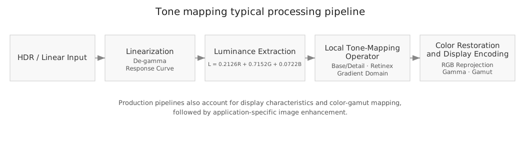
Figure 3: Typical processing pipeline from linearization to luma domain tone mapping.
In subsequent various local tone mapping algorithms, although the mathematical details and implementation methods vary, most of them can be embedded in the above-mentioned overall pipeline: the core operation is first completed in the linear brightness domain, and then combined with the color space and display device characteristics to generate the final visual output.
3. Basic idea of local tone mapping
3.1 The need to maintain local contrast and details
When the human eye observes an image, it is particularly sensitive to local contrast and edge details - even if the overall contrast is not high, as long as the local structure is clear, the picture will be considered "detailed and textured". From an engineering perspective, the goal of local tone mapping can be summarized as follows: Try to preserve or even slightly enhance local contrast and high-frequency details while compressing large-scale brightness changes.
This often means adopting different strategies at different "spatial frequencies":
Perform strong compression on low frequencies (large-scale brightness changes, such as sky vs. ground) to avoid overexposure or blackout;
Perform weak compression or moderate enhancement on mid-to-high frequencies (textures, edges) to keep textures visible and edges sharp;
Suppress non-structural high-frequency components such as noise to prevent "noise amplification".
3.2 Decomposition framework based on “base + details (multi-scale brightness decomposition)”
Most local tone mapping algorithms can be abstracted into a "base + detail" decomposition framework:
Perform edge-preserving smoothing/filtering on the original brightness map to obtain a slowly changing base (base layer);
Subtract the base from the original image (or subtract in the logarithmic domain) to obtain details (detail layer) containing local structures;
Apply strong dynamic range compression to the base and slight compression or enhancement to details;
The processed base and details are recombined to generate the output brightness.
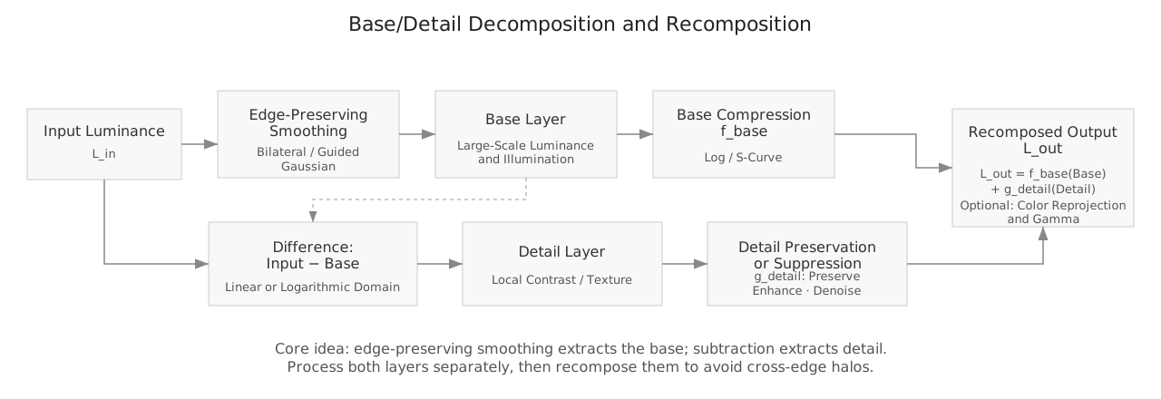
Figure 4: Common multi-scale brightness decomposition decomposition process.
In engineering implementation, the choice of filter to obtain the base layer (Gaussian filtering, bilateral filtering, edge-preserving filtering, Laplacian pyramid, etc.) determines the visual style, Halo risk and computational overhead of the algorithm.
3.3 Halo artifacts and structural distortion issues
The most common visual problem with local tone mapping is Halo artifacts: halos of light and dark around strong contrasting edges. Most of the root causes can be traced back to "base filtering crossing edges that should not be crossed": When the base is over-smoothed on both sides of the object, it is easy to produce abnormal brightness transitions near the boundaries when recombined with details.
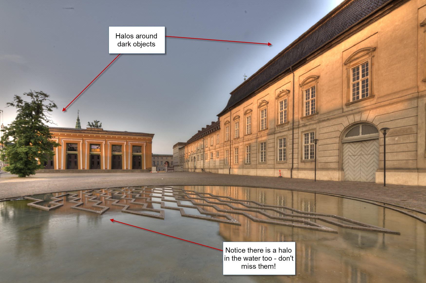
Figure 5: Example of a Halo artifact—a glowing halo at the intersection of light and dark (red arrow).
Commonly used suppression strategies in engineering include:
Use stronger edge-preserving filtering (edge-preserving filtering, bilateral grid, etc.) to reduce cross-border smoothing;
Use multi-scale decomposition and limit the compression intensity of each scale to avoid excessive reversal at a single scale;
Directly constrain the gradient amplitude in the gradient domain or Laplacian domain to prevent obvious abnormalities in the gradient direction and magnitude.
3.4 Computational complexity and real-time trade-off
Local operations mean higher computational costs: a large number of neighborhood operations, iterative solutions, and multi-scale decomposition will significantly increase the computing power requirements. In 4K video or even real-time game rendering scenarios, the tone mapping budget is often only a few milliseconds, so a realistic trade-off must be made between "effect" and "speed".
Common optimization methods in practice include:
Use techniques such as separable filtering and integral maps to reduce convolution from O(r²) to O(1) or linear complexity;
Perform local processing in a lower resolution space and then upsample to the original resolution;
Use compact data layout and shared memory on the GPU to reduce memory access overhead;
Provide "high quality/low quality" multi-level implementation for different platforms, switching according to device performance.
4. Classic local tone mapping algorithm
4.1 Laplacian/Gaussian pyramid multi-scale brightness decomposition method
Laplacian/Gaussian pyramid type multi-scale brightness decomposition method uses multi-scale blur and bandpass decomposition to split the image into slowly changing base and detail components of different scales, and then differentially compresses and reorganizes each scale component to compress the overall contrast while retaining local details as much as possible.
The algorithm idea can be simplified as:
Construct multi-scale fuzzy brightness maps (for example, using Gaussian convolution, from small to large scales);
For each pixel, compare the local contrast at different scales and select the most appropriate scale as the local adaptive brightness;
Use this "adaptive brightness" to design a local compression function so that bright areas are compressed and dark areas are improved;
Global contrast and brightness fine-tuning of the compression results is performed and mapped back to RGB space.
In engineering practice, the above-mentioned multi-scale processing is usually achieved with the help of Laplacian/Gaussian pyramid structures: the amplitudes of the bandpass components are adjusted separately on multiple scales, thereby differentially compressing and enhancing structures of different sizes.
At the code level, key implementation points include: efficiently constructing multi-scale blur maps, selecting appropriate contrast measures and thresholds, and ensuring stability in boundary condition processing and floating point accuracy. The advantages of this type of method are clear concepts and intuitive parameter meanings, but the implementation is slightly complicated and Halo is prone to occur in extreme scenarios.
4.2 Tone Mapping based on Bilateral Filter
Bilateral filtering is a classic edge-preserving filter that simultaneously weights the two dimensions of spatial distance and intensity difference to preserve edges while blurring flat areas. Using bilateral filtering for base layer extraction is the starting point for many local tone mapping algorithms.
Typical engineering process:
Apply bilateral filtering to the input image in the logarithmic brightness domain to obtain a smooth basis;
Subtract the base from the original image to obtain the detail component;
Apply a nonlinear compression function to the substrate (such as logarithmic or exposure-based S-curve);
Detail components are retained or enhanced by a certain proportion and recombined with the compressed base.
Since bilateral filtering requires a large amount of calculation, various acceleration techniques (such as hierarchical approximation, bilateral grid, block approximation, etc.) are often used in practice, or bilateral filtering is run at a lower resolution and then interpolated back to the full resolution.
4.3 Tone Mapping based on edge preserving filter (Guided Filter)
Edge-preserving filtering assumes that the output is a linear function of the guided image within a local window, thereby obtaining a filter with edge-aligned properties that can be implemented in linear time. Compared to bilateral filtering, it is more suitable for use in high-resolution images and real-time applications.
In local tone mapping, a common approach is:
Select the brightness image or grayscale image as the guide image, and use edge-preserving filtering to obtain a smooth base;
The detail map is obtained through difference, the dynamic range is compressed on the base, and the details are lightly enhanced or denoised;
After reorganization, it is sent to the subsequent color recovery and display encoding stages.
When adjusting parameters, you need to focus on the window radius and regularization parameters, which directly affect the smoothness of the base and Halo risk.
4.4 Methods based on Retinex theory
Retinex theory decomposes images into slowly varying luminance components and rapidly varying reflectance components, making it naturally suitable for local contrast enhancement and tone mapping. Multi-scale Retinex simulates the brightness adaptation behavior of the human eye in different visual fields by smoothing and normalizing across multiple scales.
When implementing projects, you usually need to consider:
Choose an appropriate smoothing kernel and scale combination (small scale enhances local details, large scale controls overall brightness);
Perform noise suppression on lighting estimates to prevent reflectance maps from amplifying noise;
Combine the color recovery module on color images to avoid obvious color casts.
4.5 Local histogram method (CLAHE, etc.)
The local histogram method enhances local contrast by counting the brightness distribution in a small area and performing histogram equalization or restricted equalization on each area. A typical representative is Contrast Limited Adaptive Histogram Equalization (CLAHE).
Algorithmically, the image is generally divided into regular grids, the cropped histogram and cumulative distribution function are calculated within each grid, and then the mapping results are interpolated between grids to avoid blocky boundaries.
Key points in engineering practice include:
Choose an appropriate grid size: if it is too small, it will easily produce noise and local over-enhancement; if it is too large, it will lose the local adaptive effect;
Set an appropriate contrast clipping threshold (clip limit) to control noise amplification and brightness stretching intensity;
Use bilinear interpolation or smoother transition strategies between grids to reduce blocking artifacts;
In HDR pipelines, local histogram methods are often used in combination with global curves or multi-scale brightness decomposition frameworks to obtain a more stable visual style.
4.6 Overview of other representative methods
In addition to the above methods, the following technical routes are also common in engineering projects:
Reinhard local operator: A classic multi-scale local adaptation method proposed early on, which selects an adaptation scale by comparing the local contrast in the multi-scale fuzzy brightness map, and then designs a compression function accordingly. It is widely cited in the literature, but the implementation is slightly complicated, and Halo is easy to occur in extreme scenes.
Gradient domain method + Poisson reconstruction: compress large gradients in the gradient domain, moderately retain small gradients, and then reconstruct the brightness map by solving the Poisson equation; theoretically it is easy to control the local contrast, but in engineering it is more sensitive to solvers, boundary conditions and residual corrections.
Heuristic hybrid method: splicing a simple global curve with a local enhancement module to achieve a "pseudo-local" effect while ensuring real-time performance.
5. Self-developed local tone mapping algorithm
5.1 Algorithm Overview
Our self-developed algorithm combines HDR dynamic range compression with local tone mapping: it can compress extremely wide brightness ranges in HDR mode and steadily improve local contrast under linear/low dynamic input. The core is scene-aware brightness redistribution and detail preservation: it first adaptively compresses the dynamic range of high and low intervals based on brightness distribution, then uses controlled gain to improve local contrast, and cooperates with exposure and saturation control to ensure color stability and consistent look and feel under complex lighting such as backlighting, night scenes, and indoor highlights.
5.2 Key advantages
Halo suppression: Use an edge-preserving smoothing strategy to limit cross-border diffusion and constrain detail gain at brightness gradients to reduce halos at the intersection of light and dark.
Color stability: Completes compression and enhancement in the brightness domain, and implements adaptive saturation control on the chroma component to maintain the original saturation and chroma without color cast.
High dynamic range: Use segmented compression for highlights and shadows to preserve subjective layering while avoiding overexposure and blackout.
Detail enhancement: Improve local contrast and texture clarity within a safe range to avoid overshoot and artifacts.
Noise Control: Suppresses noise amplification in dark and flat areas, maintaining a balance between detail enhancement and smoothing.
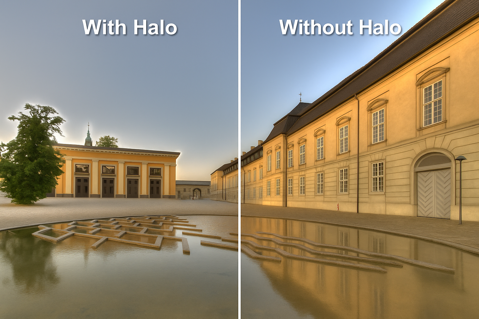
Figure 5-1: Halo suppression example, comparing the halo control performance of different treatments under strong light.
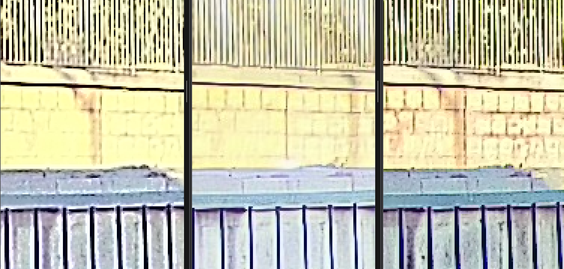
Figure 5-2: Example of detail enhancement (left: mainstream ISP effect 1, middle: mainstream ISP effect 2, right: self-developed algorithm), comparing texture clarity and artifact control.
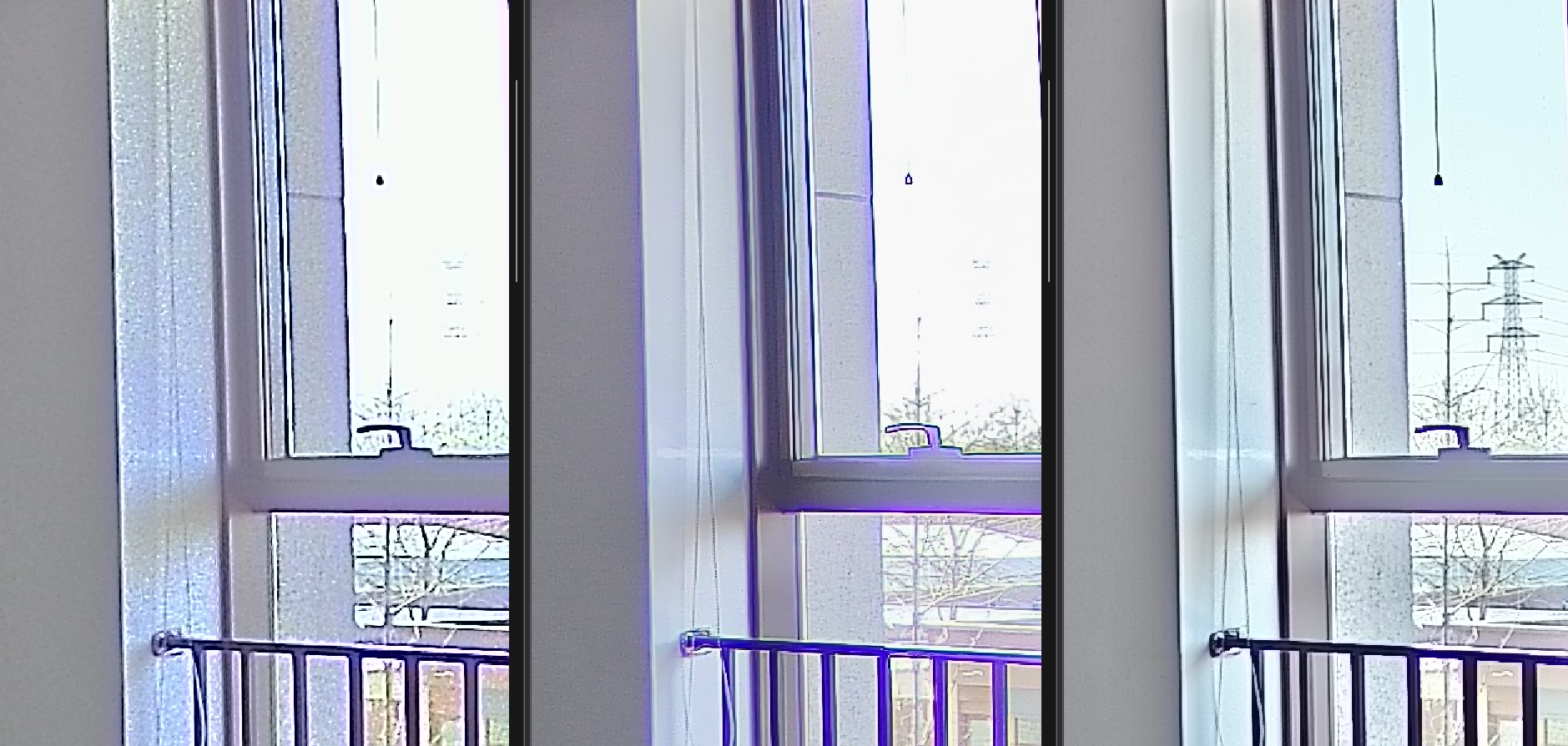
Figure 5-3: Comparison of dynamic range and noise control in large backlight scenes (left: mainstream ISP effect 1, middle: mainstream ISP effect 2, right: self-developed algorithm).
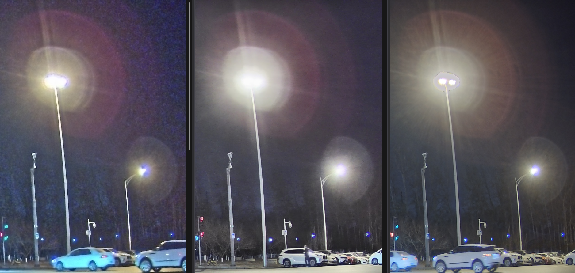
Figure 5-4: Comparison of highlight area details and halo control of a high dynamic range night scene example (left: mainstream ISP effect 1, middle: mainstream ISP effect 2, right: self-developed algorithm).
6. Deep learning driven local tone mapping
6.1 Data-driven HDR to LDR mapping idea
Deep learning methods no longer explicitly design specific filters and compression functions, but directly learn the mapping from input to output through a large number of HDR–LDR sample pairs. Training data can come from high-quality manual color correction results, in-house annotated data from professional and mobile cameras, or public HDR datasets.
From an engineering perspective, the key issues are:
Build a diverse data set covering typical scenes (indoor, backlight, night scene, strong light, distant view, etc.);
Ensure that labels (target LDR images) are consistent in style to avoid the network learning conflicting “aesthetics”;
Dealing with alignment issues: Multi-frame HDR or multi-exposure inputs require precise registration to reduce ghosting introduced by motion.
6.2 Network structure design (U-Net, multi-scale CNN, Transformer, etc.)
Local tone mapping is a "low-level vision + style enhancement" task. The network structure generally has the following characteristics:
Use an encoder-decoder (U-Net) structure to obtain a large receptive field while maintaining details;
Process features at multiple scales (such as pyramid features or variable atrous convolution), taking into account global exposure and local contrast;
Introduce attention modules or Transformer blocks to model long-range dependencies and cross-region correlations.
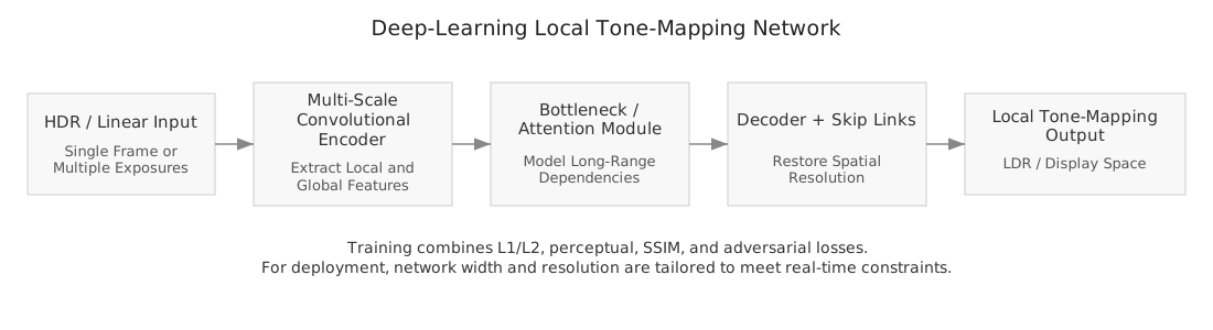
Figure 6: Typical deep learning local tone mapping network structure.
6.3 Perceptual loss and contrast constraints
It is often difficult to ensure satisfactory visual quality using only L1/L2 pixel loss, so composite loss is usually used in engineering:
Perceptual loss (based on pre-trained network features such as VGG) to ensure the overall style and structure;
Structural similarity (SSIM/MS-SSIM) loss to enhance local contrast and edge consistency;
Gradient or Laplacian loss suppresses over-smoothing and protects important details;
Adversarial loss (GAN) makes the output distribution closer to real photos and reduces the "network smell".
6.4 Comparison and fusion with traditional local operators
The advantages of deep learning solutions are strong expressiveness and the ability to learn complex mappings end-to-end, but it also brings problems such as strong data dependence, poor interpretability, and high deployment costs. In engineering practice, common compromise strategies include:
Encapsulate traditional filtering modules (bilateral, edge-preserving filtering, pyramid, etc.) into differentiable operators and embed them inside the network;
Use a lightweight network to predict a small set of parameters, and then drive the traditional local tone mapping operator to run, realizing "learning parameters + traditional algorithm";
In mobile deployment, use the network to classify scene types and global exposure, and then select preset local processing strategies.
7. Typical application scenarios
7.1 Security monitoring and low-light scenes
In security monitoring systems, cameras often need to cover an extremely wide brightness range: including direct light and highlight areas, as well as low-illumination areas such as shadows and corners. Local tone mapping can significantly improve the visibility of dark details and key areas such as faces and license plates without over-compressing overall contrast.
In engineering, common challenges in this scene include: local enhancement and amplification of noise under low light, color cast caused by infrared fill light, Halo caused by strong point light sources, etc. Therefore, actual systems usually jointly design local tone mapping with noise reduction, dehazing, motion detection and other modules, and adaptively adjust the intensity according to the ambient brightness.
7.2 Autonomous driving and on-board cameras
Autonomous driving and advanced driver assistance systems (ADAS) rely on on-board cameras to stably perceive the environment under complex lighting conditions: such as tunnel entrances and exits, backlight driving, nighttime street lights and oncoming car lights and other high-contrast scenes. Proper local tone mapping helps improve visibility of road surfaces, pedestrians, traffic signs, and lane lines.
In this scenario, the algorithm design must strike a balance between "human eye perception" and "machine vision robustness" to avoid artifacts, smear or local exposure instability caused by excessive enhancement, thereby affecting the reliability of the detection and segmentation model. In practical systems, local tone mapping is often tightly coupled with automatic exposure, HDR synthesis, and deep learning perception modules.
7.3 Local processing in mobile phone camera HDR algorithm
The multi-frame HDR algorithm for mobile phone cameras usually includes steps such as multi-frame alignment, synthesis, noise reduction, and local tone mapping. Local tone mapping directly determines the user's subjective experience of "tolerance" and "details", and is also one of the key points of differentiation among major manufacturers.
Due to the limited computing power and power consumption of mobile terminals, local processing here usually uses lightweight operators or networks, and is designed to be highly coupled with modules such as exposure, AWB, and noise reduction.
7.4 Medical imaging scenarios
In medical imaging (e.g., X-ray, CT, MRI), local tone mapping is used to highlight lesions or tissue structural details. Unlike consumer applications, the degree of artifacts and local contrast enhancement must be carefully controlled to avoid misleading diagnostic results.
In medical scenarios, more attention is usually paid to the correspondence between grayscale distribution and tissue structure. Many local processes are only allowed to be performed within a proven dynamic range compression framework, and need to match medical display standards (such as DICOM GSDF curves) and diagnostic workflows. Some systems will provide two sets of parameters, "diagnosis mode" and "display mode", to distinguish serious diagnosis from teaching and demonstration purposes.
7.5 Industrial inspection scenarios
In industrial inspection (such as weld inspection, defect inspection), local tone mapping is used to highlight the details of defective areas such as scratches, pores, cracks, etc. It is necessary to enhance visibility while avoiding the introduction of artifacts that are easy to misjudge.
In industrial inspection, local tone mapping is often used in conjunction with threshold segmentation, edge detection, and defect classification algorithms to improve the visibility of fine structures. This type of application places more emphasis on repeatability and stability. It is necessary to ensure the consistency of processing effects between different batches and different equipment, so as to facilitate the formulation of quantitative judgment standards.
8. Development trends and open issues
8.1 From manual design to end-to-end learning
From early hand-designed local operators to today's end-to-end learned HDR–LDR networks, the development path of local tone mapping is similar to many image processing tasks. A future trend is to integrate more engineering experience and physical priors into deep network structures to form an “interpretable and learnable” hybrid framework.
8.2 Joint modeling of perception model and display device characteristics
Better modeling of the human visual system and display device characteristics is another key direction to improve the quality of tone mapping. This includes:
More accurate brightness adaptation and contrast sensitivity models;
Model the brightness, contrast, and color gamut characteristics of different display devices (mobile phones, TVs, VR headsets);
Embed these models into optimization goals or network training processes.
8.3 Unified framework with other image enhancement tasks
Local tone mapping is highly related in nature to tasks such as dehazing, low-light enhancement, and local contrast enhancement: they all involve the redistribution of local brightness and contrast. It is an attractive direction to build a unified enhancement framework (such as based on Retinex or deep network) to adapt the same model to multiple tasks.
8.4 Interpretability and parameter controllability
As deep learning methods account for an increasing proportion of imaging systems, how to maintain the interpretability of algorithms and controllability of parameters has become a common concern for engineering teams and artists. This includes:
Connect network internal features with traditional concepts (brightness, contrast, multi-scale brightness decomposition, etc.);
Provide a controllable interface so that users or upper-layer systems can stably control "strength" and "style";
Design visual tools to help adjust parameters and locate problems.
9. Summary
As a key link between HDR imaging and limited display devices, local tone mapping has experienced the evolution from classic filtering and multi-scale decomposition, to Retinex, gradient domain methods, to deep learning and hybrid frameworks in the past few decades. Although the technology continues to change, the core goal remains the same: to compress dynamic range while retaining local contrast and structural details as much as possible to provide natural, informative and visually comfortable images.
From an engineering practice perspective, successful local tone mapping solutions often have the following characteristics:
In typical scenarios, the visual effects are stable, the style is unified, and artifacts and failure cases are controllable;
The computational complexity matches the computing power of the target platform and is easy to deploy on GPU/mobile terminals;
It has certain interpretability and adjustability, which facilitates parameter adjustment and long-term maintenance.
With the continued development of display technology, perceptual models and deep learning, local tone mapping will remain an important part of computational photography, rendering and visual enhancement systems, and is expected to be integrated with more image enhancement tasks to form a more unified and intelligent visual processing framework.